Introduction
This section describes the format of nesting orders. All data are sent in a single request. The data includes parts, formats, and optimization time. The easiest way to get started is to look at the examples in Getting Started
Request
An order is sent using a POST request to https://api.nesting.almacam.com/new using the following header:
Authorization: Bearer ...
Content-Type: application/json
The Nesting Job Data Structure
Three components among five are mandatory to make a complete nesting order:
| Attribute | Value | Description |
|---|---|---|
parts |
array, required | Description of the parts to nest |
sheets |
array, required | Description of the formats available for the nesting |
time |
float, required | The optimization time in seconds |
pre_nestings |
array, optional | Forces some nestings to be used |
compact |
string, optional | Post-process results by "compacting" the parts |
Parts
A part is described by its geometry, some optional properties, and its instances:
| Attribute | Value | Description |
|---|---|---|
geometry |
array, required | The outlines of the shape |
holes |
array, optional | The holes of the shape |
instances |
array, required | The array of actual instances |
protection_offset |
float, default = 0.0 | The minimal distance with other parts |
geometrythe external outlines of the part to nest as an array of contours.holesthe holes inside the geometry, if any, described with an array of contours like forgeometry.instancesdescribes how many times and in which conditions this geometry can be nested: quantities, orientations allowed, ...protection_offsetfor quality reasons, it is often necessary to make sure that parts are not nested too close from each other. This defines the minimum distance between one of these part and another nested part.
Contours
A contour is a closed line that represents a geometry. There are two kinds of contours: polygonal and arc-based. In any case they shall not self-intersect.
The simplest is the polygonal contour, described with an array of
vertices. One vertex is itself a plain array of its two coordinates:
[x, y]. If the last vertex of the array is different from the first,
they will be connected by a segment to close the polygon.
The arc-based contour is an array of elements containing information about the vertex, and the arc linking it to the next vertex. The API provides three different ways to describe an arc: with a bulge value, a sagitta length or with the center of the circle. While the latest is the most common, the two previous are prefered as they are less error prone.
The possible attributes for an arc are:
| Attribute | Value | Description |
|---|---|---|
x |
float, required | X coordinate of the vertex |
y |
float, required | Y coordinate of the vertex |
sag |
float, optional | Sagitta of the arc |
bul |
float, optional | Bulge of the arc |
cir |
dict("x": float, "y": float, "dir": boolean), optional | Circle representing the arc |
x,ythe coordinates of the current vertex, starting the arc. They also define the end point of the previous arc, if the previous element is indeed an arc.sagthe sagitta of the arc between the current vertex and the next one. A sagitta is signed and a positive value means the arc is on the right-hand side of the chord. If 0, a segment joins both vertices. The last sagitta refers to the arc between the last vertex and the first, closing the contour. There must be no intersections. If an element contains asagattribute, it cannot contain any other attributes thanxandy.bulthe bulge of the arc between the current vertex and the next one. A bulge is signed and a positive value means the arc is on the right-hand side of the chord. If 0, a segment joins both vertices. The last bulge refers to the arc between the last vertex and the first, closing the contour. There must be no intersections. If an element contains abulattribute, it cannot contain any other attributes thanxandy.cirthe circle representing the arc between the current vertex and the next one. It contains the coordinatesxandyof the center, anddirthe direction of the arc. IfdirisTrue, then the arc direction is counter-clockwise on the circle, and ifFalsethe arc direction is clockwise. If the circle center is not on the perpendicular bisector of the segment between the 2 vertices, it will be projected on it for further computations to ensure consistency. If an element contains acirattribute, it cannot contain any other attributes thanxandy.
If only x and y attributes are defined, a segment is used to join the next point.
Examples:
Polygonal contour of a simple square:
[
    [0.0, 0.0],
    [0.0, 1.0],
    [1.0, 1.0],
    [1.0, 0.0]
]
Arc-based contour of a simple circle defined by sagittas:
[
    {
        "x": 0.0,
        "y": 0.0,
        "sag": 0.5
    },
    {
        "x": 1.0,
        "y": 0.0,
        "sag": 0.5
    },
]
Arc-based contour of a simple circle defined by bulges:
[
    {
        "x": 0.0,
        "y": 0.0,
        "bul": 1.0
    },
    {
        "x": 1.0,
        "y": 0.0,
        "bul": 1.0
    },
]
Arc-based contour of a simple circle defined by circles:
[
    {
        "x": 0.0,
        "y": 0.0,
        "cir": {
            "x": 0.5,
            "y": 0.0,
            "dir": True
        }
    },
    {
        "x": 1.0,
        "y": 0.0,
        "cir": {
            "x": 0.5,
            "y": 0.0,
            "dir": True
        }
    },
]
Notions of geometry
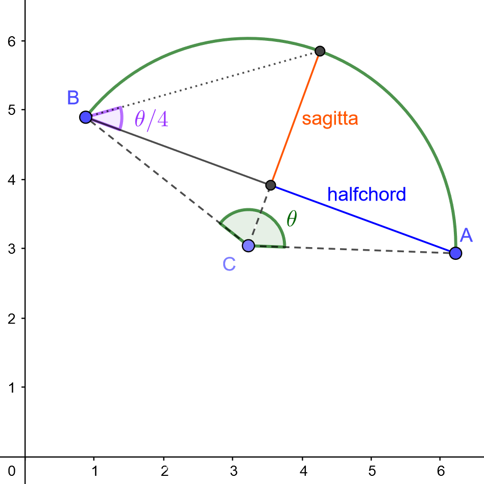
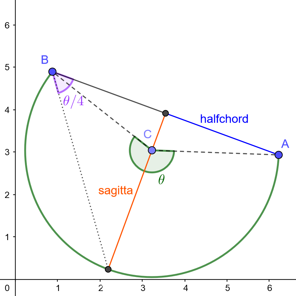
The sagitta of an arc is the distance between the midpoint of the chord and the midpoint of the arc. A sagitta value of half the chord represents a semi-circle.
The bulge is the ratio between the sagitta and half the chord. If \theta is the angle made by the arc around the circle center, then the bulge can also be seen as tan(\theta/4). A bulge value of 1 represents a semi-circle.
In the figures below, there is an arc from A(6.22, 2.94) to B(0.88, 4.9), that has its circle center at C(3.23, 3.04). The left figure represents the counter-clockwise arc of the circle, which happens to be on the right-hand side of the chord [\overrightarrow{AB}]. It has a sagitta of 2.06 and a bulge of 0.73. The right figure represents the clockwise arc of the circle, which happens to be on the left-hand side of the chord. It has a sagitta of -3.92 and a bulge of -1.38 (notice the negative sign indicating the fact that the arc is on the left-hand side of the chord).
| Counter-clockwise arc | Clockwise arc |
|---|---|
 |
 |
Both these arcs can be defined as follows:
[
    ...,
    {
        "x": 6.22,
        "y": 2.94,
        ARC_INFO,
    },
    {
        "x": 0.88,
        "y": 4.9,
        ...
    },
    ...
]
With ARC_INFO being one of the values below:
| Type | Counter-clockwise arc | Clockwise arc |
|---|---|---|
| Sagitta | "sag": 2.06 |
"sag": -3.92 |
| Bulge | "bul": 0.73 |
"bul": -1.38 |
| Center | "cir": {"x": 3.23, "y": 3.04, "dir": True} |
"cir": {"x": 3.23, "y": 3.04, "dir": False} |
Part Instances
| Attribute | Value | Description |
|---|---|---|
orientations |
array(Orientation), required | The orientations allowed for this part instance |
id |
int, required | Unique identifier of the part instance |
quantity |
int, default = 1 | The quantity of this part instance |
priority |
int, default = 0 | Hint to place high-priority parts before lower-priority ones |
idthe unique identifier of the part, it is used later to retrieve a part in a nesting resultpriorityThe algorithms will greedily place high-priority parts before lower ones. This is not a strong enforcement, e.g. instances with lower priorities might be nested before higher ones if the latter do not fit.
Orientations
Orientations are described in degrees, going counterclockwise. There
are two kinds of orientations: punctual and range-based. In both
cases, there is an optional flip boolean to apply a symmetry along
the x axis after the rotation.
The punctual one has the following attributes:
| Attribute | Value | Description |
|---|---|---|
angle |
float, required | the angle in [0, 359.9] |
flip |
boolean, default = false | if the part must be flipped |
The range-based one defines a range of allowed orientations:
| Attribute | Value | Description |
|---|---|---|
min_angle |
float, required | the minimum angle, [0, 359.9] |
max_angle |
float, required | the maximum angle, in [min_angle, 359.9] |
flip |
boolean, default = false | if the part must be flipped |
Examples:
Free orientations without flip:
[
    {
        "min_angle": 0.0,
        "max_angle": 359.9
    }
]
Free orientations with or without flip:
[
    {
        "min_angle": 0.0,
        "max_angle": 359.9
    },
    {
        "min_angle": 0.0,
        "max_angle": 359.9,
        "flip": true
    }
]
All orientations by 90 degree steps:
[
    {
        "angle": 0.0
    },
    {
        "angle": 90.0
    },
    {
        "angle": 180.0
    },
    {
        "angle": 270.0
    }
]
A single angle allowed, with or without flip:
[
    {
        "angle": 0.0
    },
    {
        "angle": 0.0,
        "flip": true
    }
]
Sheets
Sheets represent the rectangular formats available to nest the parts.
Sheets are described using the following attributes:
| Attribute | Value | Description |
|---|---|---|
length |
float | The length of the sheet, -1 for infinite |
height |
float | The height of the sheet |
contour |
contour, default = None | Non rectangular sheet outline, incompatible with length/height |
id |
int, required | The unique identifier of the sheet |
quantity |
int, default = 1 | The quantity of this sheet |
border_gap |
float, default = 0.0 | Avoid parts to be nested near the edge by defining a border gap |
defects |
array(contour), default = [] | The outlines of the defects |
-
length/heightis the primary way to define a rectangular sheet. -
contourcan be used instead oflength/heightto define non-rectangular sheets. It musts not be used for rectangular ones. The contour description is identical to the geometry description of parts. See section Contours for details. Please note thatcontourandlength/heightare mutually exclusive. WARNING: the bottom left corner of the sheet's bounding box must be the point (0, 0). -
defectsThey represent area on the sheet where no part can be nested. The protection area of a shape is allowed to intersect the defects however. The defect description is identical to the geometry description of parts. See the section Contours for details.
Pre-nestings
It is possible to determine in advance positions and orientations of some parts on some sheets. This is useful for instance to fill an existing nesting with more parts. Or if domain-specific constraints require a special part to be nested at a specific place.
Overlaps are not checked, parts can be placed anywhere, not necessarily fully inside the sheet. The pre-nestings information (sheets, parts, orientations, quantities, ...) must be a valid subset of the available parts and sheets. The pre-nested quantities are substracted from the initial ones.
Pre-nestings are very similar to nesting results. Many pre-nestings can be defined. A pre-nesting contains the following attributes:
| Attribute | Value | Description |
|---|---|---|
sheet |
int, required | the user-provided id of the sheet |
nested_parts |
array, required | the nested parts contained in that pre-nesting |
quantity |
int, default 1 | the multiplicity of this pre-nesting |
And a nested-part is defined as follow:
| Attribute | Value | Description |
|---|---|---|
id |
int, required | the user provided id of the pre-nested part |
angle |
float, required | the orientation of the pre-nested part |
flip |
boolean, required | true if the part is placed symmetrized along the x axis |
position |
array(float), required | the carthesian coordinates [x, y] of the nested part |
In the following example, one of the part is placed on top right corner of the first sheet. The 9 remaining parts will then be placed automatically by the algorithm, using new sheets if necessary.
{
    "parts":
    [
        {
            "geometry": [[[0, 0], [1, 0], [1, 1], [0, 1]]],
            "instances":
            [
                {
                    "id": 123,
                    "quantity": 10,
                }
            ]
        }
    ],
    "sheets":
    [
        {
            "height": 5.0,
            "length": 10.0,
            "id": 456,
            "quantity": 4
        }
    ],
    "pre_nestings": [
        {
            "quantity": 1,
            "sheet": 456,
            "nested_parts": [
                {
                    "position": [9.0, 4.0],
                    "angle": 0.0,
                    "id": 123,
                    "flip": false
                }
            ]
        }
    ],
    "time": 3.0
}
Compact
| Attribute | Value | Description |
|---|---|---|
compact |
top-left or bottom-left |
Post-process each nesting by pushing all parts in a direction |
The use of this attribute will add a post-processing step after the standard optimization to push all the parts in a given direction. In the final results, all the parts will be in "contact".
Depending on the number of nestings to post-process and on the shapes complexity, the use of this attribute might require a significant amount of extra time.
Pre-nested parts are not affected.
JSON-Schema
The json-schema describing the nesting order datastructure can be found here: job_schema.json. It allows to check the validity of the jobs before sending.
Responses
201
Content-Type: application/json

{
    "message": "Nesting order submitted",
    "nesting_order_id": 1453303923246998305
}
400 - See Error 400 for details
Content-Type: application/json

{
    "message":"An error occurred",
    "errors":[
        {
            "path":["parts", 0, "instances", 0, "orientations"],
            "message":"[] is too short",
            "error_code":-3000
        }
    ]
}
401
Content-Type: application/json

{
    "message": "Incorrect authentication"
}
406
Content-Type: application/json

{
    "message": "This API requests json format"
}